5 inch drone build
This is still a work in progress. Only for education purposes. No ai writeup
Specs
| Part | Description | Price (Euro) |
|---|---|---|
| Cyclone T5045 | Propellers | 6 |
| RS2205 | Motors (2300KV) | 25 |
| QAV250 | Frame | 16 |
| F4V3S Plus | Flight Controller 📦Bought in pack for 73 | 25 |
| 60A ESC | Electronic Speed Controller, 📦Bought in pack for 73 | 25 |
| 800TVL Analog Camera | FPV Camera, 📦Bought in pack for 73 | 15 |
| VTX1000 | Video Transmitter, 📦Bought in pack for 73 | 10 |
| FS I6 2.4g Controller | Transmitter | 48 |
| FS IA6B 2.4g Receiver | Included with FS-I6 | 0 |
| FS-SM100 | Optional student i6 usb module | 6.9 |
| EV800D | FPV Goggles | 86 |
| IMAX B6 | 1-6s Battery Charger | 22.6 |
| Batteries | 3s 1800mah 60c|3s 1500mah 60C|2x 3s 2200mah 30c|2x 4s 850mah 70c | 71 |
| Misc | Solder, Velcro, replacement screws, zip-ties, printed camera mount | ~0 |
| Total | 360 |
Build Notes
There are lots of basics one has to get staight to understand fpv drone
flying, like that a 5 inch drone not 5 inch in diameter but when talking
about drone sizes we talk about the propellers.
Frame
Building the drone is straight forward. The frame has to be assembled. Here I already lost a screw but that only bothers viusally. Usually the frames are symmetric so you should worry about it. Just build however it fits. Next we can screw on the motors.Motors
It is important to note that the spinning direction of the motors on a drone are standarized. In clockwise (CW) spinning motors we secure the blade with a normal right handed threaded nut (tighten clockwise), that prevents it from loosening. But on counter clock wise (CCW) spinning motors we have a left hand thread (loosen clockwise). Don't loose your left hand threaded nut, chances are you cannot just buy one in the hardware store. Here is the default motor spinning configuration you have to keep in mind before mounting the motors.Some motor guard will be 3d printed in the future to protect the motors when crashing.
All nuts have nylon rings to prevent them from loosening due to vibrations more on that later.
ESC
After building the farme we are putting 4 long m3 screws through the frame. Here we can mount the ESC and connect the motors. The motors are 3 phase synchronous motors. Solder the wires in groups of 3 no matter the order. The rotation of the motors can be reversed in post using the software. We are just soldering the 12 motor wires total to the ESC.Flight Controller
 After that is done we put the flight controller on the stack. The order
of what to put where is not mandatory but simply a guideline. The white
silkscreen arrrow on the flight controller is the heading.
After that is done we put the flight controller on the stack. The order
of what to put where is not mandatory but simply a guideline. The white
silkscreen arrrow on the flight controller is the heading.
Betaflight
Betaflight is the software that runs on our flight controller. But first we might need to flash it. After flashing we can check the motors and let them spin in the correct direction. In the ports tab we have to enable the port that will receive the users control inputs. For example in the column RX I enabled UART6.Controller RX
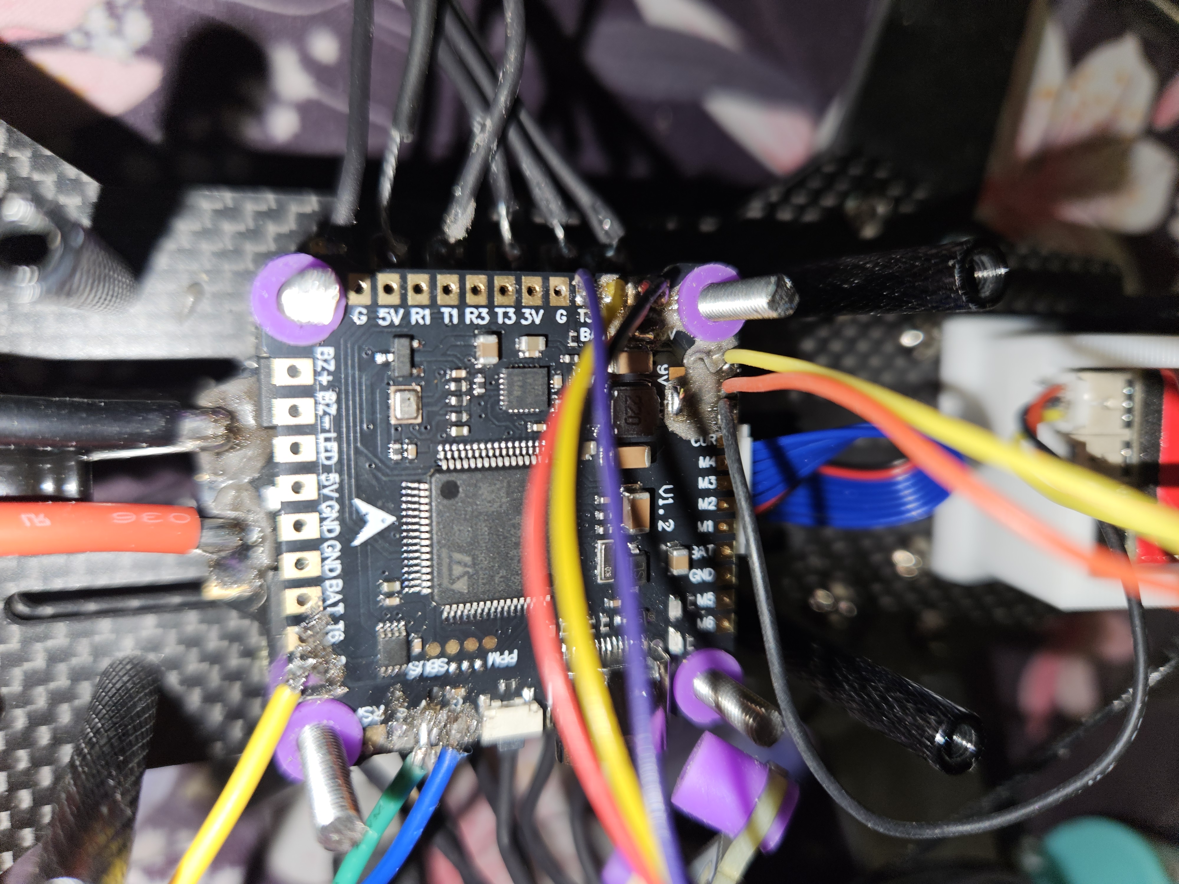
The FS-IA6B (small black dongle) gets the control inputs from the controller that the users has in their hands (here i6). Using a oszi we can verify that the module (ia6b) is changing its output dependent on the users input. The output of the module uses a protocoll called IBUS. In essence we only have to connect one wire from the module (ia6b) to our flight controller.The image shows that yellow cable on the bottom right is connected to R6 (RX for port 6). This pin is soldered to the IBUS pin of the module, so is 5V and GND.
I did have trouble selecting the protocol IBUS in the receiver tab of betaflight. I'm not sure what fixed it. A fresh install helped.
Video output
There are two things needed to get a video output on your goggles: A camera and a video transmitter. As a video transmitter I use the VTX1000 and as a camera I use the Bcube 800 tvl. The wireing can be seen on the picture in section Flight Controller. It is important to know what protocol your components have.Test Flight
The shafts of the motors are not protruding enught for me to fit the nut on the shaft the whole way when the props are mounted. The nylon rings that help secure the nut is at the very top of the nut. But the shaft being so long prevented the nut from screwing on completely. Because of this I lost one of the nuts in a field. Luckily a normal right threaded nut. Now I tighten the nuts properly to prevent that (I bought replacements if I'd lose them).The batteries are not shipped yes. So I use a 3s battery that I have lying around that is rated for 4A. After pulling like 11A the battery died. The next video is me crathing severly for the first time.